-
 Group of Engineering and Systems Integration
 -
 Group of Engineering and Systems Integration
 -
 Group of Engineering and Systems Integration
 -
 Group of Engineering and Systems Integration
 -
 Group of Engineering and Systems Integration
Research
ITER Projects
ITER prototype Fast Plant System Controller (FPSC)
Project Leader: Bruno Soares Gonçalves
ITER Fast Plant System Controllers (FPSC) are based on embedded technologies and will be devoted to both data acquisition tasks (sampling rates > 1 kSPS) and control purposes in closed-control loops whose cycle times are below 1 ms. Fast Controllers will be dedicated industrial controllers with the ability to: i) supervise other fast and/or slow controllers; ii) interface to actuators and sensors and high performance network. This project aimed at the development of ITER prototype FPSC, specialized for data acquisition.
Two prototype systems were developed: i) based on the Advanced Telecommunications Computing Architecture (ATCA) standard under the responsibility of IPFN and ii) based on PXIe under the responsibility of CIEMAT. This prototyping activity contributes to the ITER Plant Control Design Handbook (PCDH) effort of standardization, specifically regarding fast controller characteristics.
Instituto Superior Técnico (IST), from Portugal lead the consortium which also includes Centro de Investigaciones Energéticas, Medioambientales y Tecnológicas (CIEMAT), from Spain and Universidade Politecnica de Madrid (UPM).
The contract had a duration of 2 years and a total budget of 1.5M€. This was the first contract awarded to IPFN directly from ITER. Since 2009 IST has had several contracts related to ITER construction for the development of remote handling systems, participates in the consosrtium that provides Provision of System & Instrumentation Engineering support to F4E, participates on the consortium for the development of the ITER neutron cameras (contributing to the development of the data acquisition system) and has recently been awarded a contract with the value of 8.5M€ for the development of the ITER Plasma Position Reflectometry Diagnostic Systems.
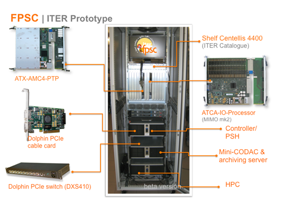
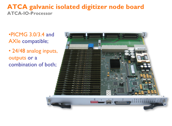
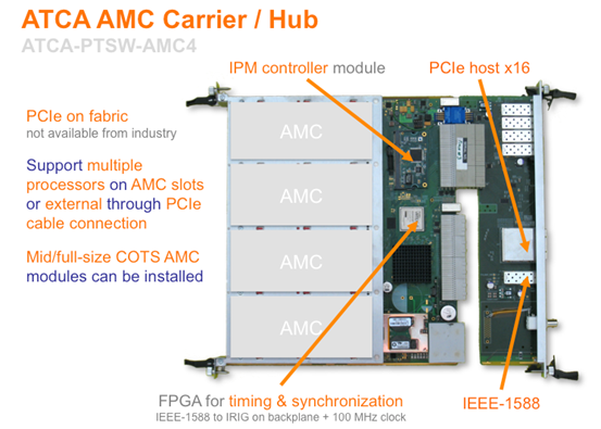
For the IST prototype, a new family of ATCA modules was developed, targeting ITER requirements. The modules comprise an AMC carrier/data hub/timing hub compliant with the upcoming ATCA extensions for physics studies and a multichannel with galvanic isolation hot-swappable digitizer designed for serviceability. The design and test of a peer-to-peer communications layer for the implementation of a reflective memory over PCI Express and the design and test of an IEEE-1588-2008 transport layer over a high performance serial link were also performed. The project brought together the work of 10 engineers per year.
ITER Plasma Position Reflectometry (PPR) Diagnostic System
ITER will be equipped with a set of plasma diagnostics to measure the plasma and first wall parameters. The functions of these plasma diagnostics are machine protection, basic and advanced control, and physics studies. The diagnostics are necessary to meet the overall ITER project requirements.
This contract aims at designing the ITER Plasma Position Reflectometry system. This diagnostic system comprises several components (antennas, waveguides, microwave electronics and real-time analysis software). The antennas and waveguides launch and receive a radio frequency signal in the range 15 – 75 GHz, which is assessed by microwave electronics and real-time analysis software to determine the density profile at the plasma edge and to estimate the distance between the plasma and the tokamak wall. This parameter is then fed to the plasma control system and used to keep the plasma stable and prevent it from touching the wall, leading to a plasma disruption which would stop the nuclear fusion process. Overall, this contract will bring together the work of some 30 physicists and engineers per year.
The contract covers R&D (including prototypes of the transmission lines and microwave electronics), engineering, quality support and managerial activities, and testing from functional specifications, up to the supply of an F4E-approved final design. This activity will be followed by the support for the production of manufacturing drawings for all components of the system as well as the final design for electronics components and for the data acquisition and real-time software.
Instituto Superior Técnico (IST), from Portugal leads the consortium of three Euratom Associates with Centro de Investigaciones Energéticas, Medioambientales y Tecnológicas (CIEMAT), from Spain; and Consiglio Nazionale delle Ricerche, Istituto di Fisica del Plasma "Piero Caldirola" (IFP-CNR), from Italy.
The contract has a duration of 4 years and a total budget of 8.5 M€. This is the 6th contract awarded to IPFN, that since 2009 has been responsible for the development of the ITER prototype Fast Plant System Controller, the development of Remote Handling Systems, participates in the consortium that provides Provision of System & Instrumentation Engineering support to F4E and to the consortium for the development of the ITER neutron cameras (contributing to the development of the data acquisition system).
Expertise and Skills for Microwaves in ITER
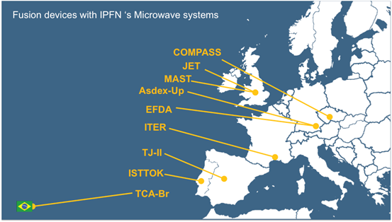
Control systems are essential for the operation of fusion devices to support the integrated automatic functioning of all systems. IPFN competencies in this area are well recognized worldwide. The contract with ITER and F4E result from a R&D vertical strategy for the development of microwave diagnostics and control and data acquisition systems, that started in the early 90’s with the sole portuguese device for research in nuclear fusion, the tokamak ISTTOK.
The main achievements of the team include the development of microwave diagnostics for several European fusion devices (Germany, UK, Spain, Czech Republic) and Brazil, and the development of data processing tools, numerical simulations and real-time control algorithms. On these developments, high relevance should be given to the contributions to the European fusion device JET (Joint European Torus) and the recent demonstration of the position control system for the tokamak ASDEX-Upgrade in Germany (2011), similar to the diagnostic being developed for ITER.
-
Theory & Modelling -
Microwave Electronics -
Data Processing & Analysis -
Plasma Physics -
Diagnostic Physics -
Integration Engineering
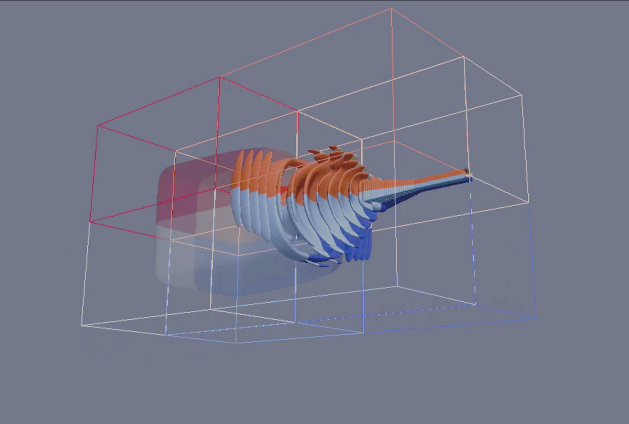
The ITER PPR in-vessel components will be subjected to ionizing radiation, both from the plasma neutrons and from gamma photons generated through nuclear reactions in the surrounding materials. The antennas and the 90º bend are directly exposed to the plasma and subjected to high neutron and photon fluxes, which will generate heat and increase their operation temperatures.
An accurate description of the in-vessel components of the PPR system was implemented in the Monte Carlo simulation program MCNP and inserted in a reference model that features the most up-to-date design information of the ITER machine. This model was used to calculate the nuclear heat loads in the in-vessel components of the PPR system.
Peak values of the order of 2.9 W/3 were obtained at the tips of the antennas, decreasing steadily in the subsequent cells as the distance to the plasma increases, down to ~0.2 W/cm3 at the back of the antenna support.
A preliminary finite-element thermal analysis showed that these nuclear heat loads, combined with the thermal radiation coming from the plasma, translate into operation temperatures that reach 480 ºC at the tips of the antennas, slightly above the maximum temperature of operation of stainless steel for ITER in-vessel components under irradiation (450 ºC). Further thermal analyses and design iterations are therefore required to improve the thermal and mechanical behavior of the system.
Nuclear heat loads in the ITER Plasma Position Reflectometry System. The picture shows the nuclear heat loads in the antennas and 90º bend of the PPR system. Peak values of the order of 2.9 W/cm3 were obtained at the tip of the antennas, which translate into operation temperatures around 480 ºC. Further design iterations are required to improve the thermal behavior of the system.
Remote Handling activities for ITER
The IST, in collaboration of IPFN (Institute for Plasmas and Nuclear Fusion) and ISR (Insititute for Systems and Robotics), has been participating in Remote Handling (RH) related projects of ITER (International Thermonuclear Experimental Reactor) since 1996. The ITER is the world's largest experimental nuclear fusion facility and the first in history to produce 500 MW.
Since 2016, IPFN is part of the consortium that won a contract, considered to be one of the biggest robotics contracts to date in the field of fusion energy.
For a brief summary, download our brochure and watch the videos below.
Since 1996, IPFN was involved in the following RH related projects:
-
Related with the Transfer Cask System in ITER -
ERB 5004 CT 96 0127-NET/96-431 (EFDA) - [1996-1997]: Conceptual study on Flexible Guidance and Docking system for ITER Remote Handling Transport Cask (main contractor: IST). -
1998 - Design study for an Air Floating System, by AeroGo, with technical assistance of IST and NNC Ltd (main contractor: AeroGo). -
ERB 5004 CT97 0088-NET/97-460 (EFDA) - [1998]: Geometric Feasibility of ITER Air Cushion Remote Handling Casks and Extensions for Free Roaming Navigation (main contractor: IST). -
F4E-2008-GRT-016 - [2009-2010] Activities related to the development of an Air Transfer System prototype and Cask Transfer System Virtual Mockup (main contractor: IST). -
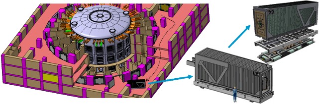
F4E-GRT-276-01 - [2011]: Optimization of Trajectories for the Cask and Plug Remote Handling System in Tokamak Building and Hot Cell (main contractor: IST). -
F4E-OMF-0577 [2016-...]: Development and supply of the ITER Cask and Plug Remote Handling System (CPRHS)
-
-
Related with the Divertor Remote Handling System in ITER -
EFDA TASK TW6-TVRWHMAN2 [2008]: DTP2 Gripper and Sliding Table Design (main contractor: VTT - Finland).
-
The IST expertise applicable in the RH maintenance system includes, but it is not limited to:
-
Navigation and Localization algorithms for mobile platforms, such as the Cask and Plug Remote Handling System (CPRHS) and the Cask Transfer System (CTS) in ITER. 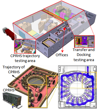
-
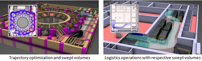
Motion Planning including manoeuvres and maximization of common parts of different trajectories. -
Remote navigation and guidance methodologies of mobile platforms with different kinematics. -
Obstacle detection and avoidance -
On-board and off-board sensor specifications, in particular laser range scanners (LIDAR systems), inertial systems and video cameras. -
Sensor systems, data acquisition, integration and processing. -
Signal processing for environmental perception -
Viewing systems and human machine interfaces to support navigation and control -
Experience on programming (e.g., MATLAB, C/C++), on CAD/CAM and Finite Elements Analysis (e.g., CATIA and ANSYS).
Project Leader: Jorge Sousa
The Control and Data Acquisition group from IPFN won one more ITER-related contract for the design and performance assessment of Integral and Proportional Data Acquisition Electronics for Real-Time Applications. This small contract with Fusion for Energy aims to open the possibility to work on the data acquisition systems for ITER magnetics diagnostics (more than 900 sensors in the whole device).
Since 2009 IST has had several contracts related to ITER construction for the development of the ITER prototype Fast Plant system Controller, for the development of remote handling systems, participates in the consortium that provides Provision of System & Instrumentation Engineering support to F4E, participates on the consortium for the development of the ITER neutron cameras (contributing to the development of the data acquisition system) and has recently been awarded a contract with the value of 8.5M€ for the development of the ITER Plasma Position Reflectometry Diagnostic Systems
The F4E Design and Performance Assessment of Integral and Proportional Data Acquisition Electronics for Real-Time Applications (F4E-OPE-442) contract is divided in four tasks: design documentation; test plan; IST tests and F4E tests.
The design documentation consists in the development of a documentation package with a detailed analysis of two modules already developed by IPFN (Figure 1), together with the manufacturing specifications of both modules.
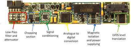
F4E chopper based digital integrator for ITER magnetics diagnostic
Project leader: Antonio Batista
F4E-OFC-361-08 contract between F4E and GTD has granted to IPFN the development and test of 8 chopper based digital integrators prototypes. The aim of this development was to choose the best prototype as a base for the final design of ITER integrators for the magnetics diagnostic.
The well-known drift problem of integrated signals has become very critical for fusion machines with long plasma discharges. The electronics offset integrated after a long time can no more be ignored.
The main goal of this work was to demonstrate that a digital integrator based on the signal chopping concept is capable of attain the ITER requirements. In particular, the ITER specifications for the integrator require a maximum flux drift of 500 uV.s/hour under a magnetic field up to 10 mT.
Several design variants of a 1 kV galvanic isolated chopper-based digital integrator have been developed and tested. The main differences between them have been the chopper ICs, ADCs, and circuitry.
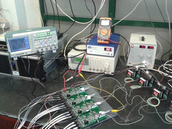
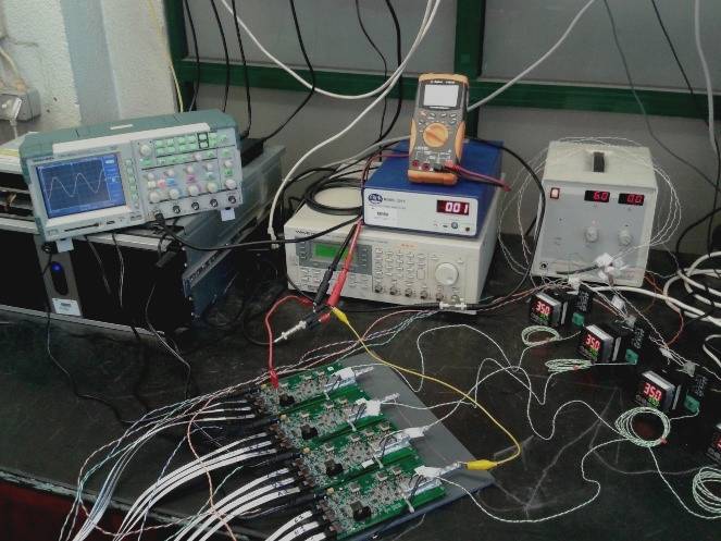
Integrator prototypes under testing
Consortium Leader: ENEA
IPFN Project Leader: Rita Pereira
The ITER Radial Neutron Camera (RNC) is a multichannel neutron collimator intended to characterise fusion plasma neutron source. The RNC diagnostic will measure the time resolved neutron emission profile for both DD and DT plasmas, providing the evaluation of fusion power and α-source density, neutron and α-source emissivity profile, core ion temperature and ion temperature profile, fusion power and total neutron flux among other relevant parameters.
The RNC is composed of two fan-shaped collimating structures, In-Port and Ex-Port installed in Equatorial Port #1: 1) In-port collimating system is located inside the port plug with 8 channels to observe the plasma edge (0.6<r/a<0.85); 2) Ex-port collimating system is located in the port interspace, consisting of two fan-shaped multichannel collimators with 10 Lines-Of-Sight in each fan to observe the plasma core (0<r/a<0.55).
The contract deals with the conduct of engineering activities in order to develop a design of the ITER RNC, together with the interfacing of the ITER Radial Gamma‐Ray Spectrometer (RGRS) into the RNC as a possible future upgrade. The main function of the RNC is to provide the neutron emissivity in a poloidal cross section of either deuterium-deuterium or deuterium-tritium ITER plasmas. The task is challenging and complex as it requires the measurement of the neutron flux (up to values in the range of 1x10⁸ n/cm2s) in a large number of detectors inserted in neutron collimators and the reconstruction of the neutron emissivity through spatial unfolding techniques. The possibility of providing additional information on further plasma parameters, such as the ion temperature profile, should be also investigated.
The contract covers R&D, engineering, quality support, technical managerial activities and testing, from functional specifications up to the supply of an F4E-approved final design. This activity will be followed by the support for the production of Manufacturing Drawings for all components of the system as well as the final design for Electronics Components and for the data acquisition electronic & software.
Instituto de Plasmas e Fusão Nuclear (IPFN) from Instituto Superior Técnico (IST), Portugal, takes part of the Consortium of six parties, (regulated by a Consortium Agreement) namely ENEA‐Frascati (coordinator), CNR‐Milan, IFJ PAN‐Krakow, IPPLM‐Warsaw, IST‐Lisbon and UNIMIB‐Milan together with another five Third Parties. IPFN provides expertise on the functional specifications/ prototyping/manufacturing/tests/interfaces for electronic & software of the RNC and RGRS diagnostic data acquisition systems.
The contract has duration of 4 years.
Provision of System & Instrumentation Engineering support to F4E (main contractor: INDRA)
Provision of System & Instrumentation Engineering support to F4E (main contractor: Vitrociset)
JET Projects
ATCA system for plasma vertical stabilization of tokamak JET
IPFN Project Leader: António Batista
The plasma Vertical Stabilization (VS) of tokamak JET is a critical system, maintaining the plasma between safe boundaries inside the machine vessel.
A Multi-Input-Multi-Output (MIMO) controller for the plasma Vertical Stabilization (VS) was implemented by IPFN and installed on the JET tokamak. The system attains a control loop-cycle time of 50 μs. The hardware, complying to the Advanced Telecommunications Computing Architecture (ATCA) standard, was specially designed to achieve such performance and consists of:- A total of 6 synchronized ATCA MIMO boards, each one with 32 analog input channels, providing up to 192 galvanically isolated channels (mainly for magnetic measurements). Each board contains DDR memory and an FPGA, which performs digital signal processing and includes a PCI Express communications interface;
- An ATCA Rear Transition Module, which comprises up to 8 galvanically isolated analog output channels for controlling the Fast Radial Field Amplifier (FRFA). An optical link to allow the digital control of the Enhanced Radial Field Amplifier (ERFA). Up to 8 EIA-485 digital IO channels for timing and monitoring information;
- An ATCA processor blade interconnected to the 6 ATCA MIMO boards through the PCI Express interface;
- All FPGAs are also interconnected by low-latency links via the ATCA full-mesh backplane.
ATCA VS front and rear views
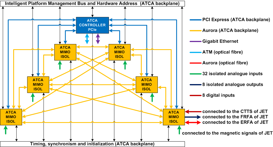
ATCA VS system architecture
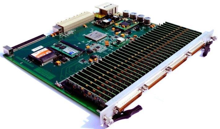
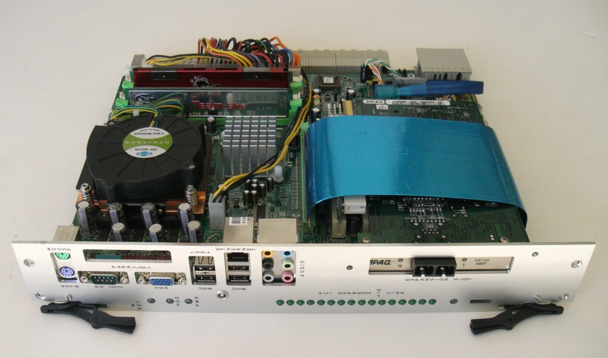
ATCA MIMO board and ATCA processor blade
The system hardware was widely replicated and installed on several fusion machines across Europe: JET, W7-X, COMPASS, RFX and ISTTOK.
IPFN Project Leader: Rita Pereira
For fusion plasma experiments that are dedicated to the ultimate utilization of controlled nuclear fusion as an energy source, the rates at which the energy producing reactions occur are, perhaps, the best indicators of this energy production. The measurement of these rates thus represents an essential diagnostic of these experiments. The quantitative spectrometry of high energy (MeV) gamma rays from nuclear reactions within the plasma offers the opportunity of determining these rates that are complementary to neutron flux measurements in the case of neutron producing reactions such as in DD or DT plasmas or which are unique in the case of aneutronic reactions such as those occurring in HD, HT, D3He or advanced fuel scenarios such as H-7Li or H-11B plasmas.
Besides the nuclear fusion reactions rate, of particular interest is the behaviour of the fusion products, such as the alpha particles from the DT or D3He reactions as their confinement is crucial to the heating of these plasmas. Gamma-ray spectroscopy provides a basis for measuring the energy spectrum of the confined alpha particles.
Gamma-ray diagnostics are important techniques used on the JET tokamak for studying confined fast ions. The intense gamma-ray emission is produced in JET plasmas when fast ions (ICRF-driven ions, fusion products, NBI-injected ions) react either with fuel ions or with the main plasma impurities such as carbon and beryllium. Gamma-ray energy spectra are recorded with collimated spectrometers (Gamma-ray Spectrometer – KM6S), while the gamma-ray emission spatial 2D-profiles are measured with the JET neutron/gamma profile monitor (Gamma-ray cameras – KN3G).
JET Gamma-ray diagnostics are increasingly demanding from the point of view of current data acquisition (DAQ) systems, both due to the larger number of detectors and to the high rate of occurrence of relevant events. Moreover, DAQ systems will play a key role when orchestrating diagnostics data from very long-duration plasma discharges, as achieving long-duration, high-performance discharges in magnetic fusion devices is one of the most important challenges faced by fusion reactors. New DAQ systems must be designed with high processing capabilities in order to provide high throughputs as well as the capability of storing significant data throughout the time of the experience to fully exploit the flux increase of the plasma provided by future high power experiments at JET and ITER.
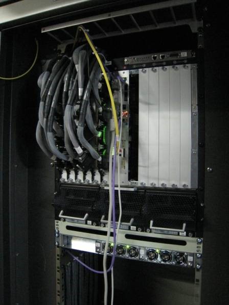
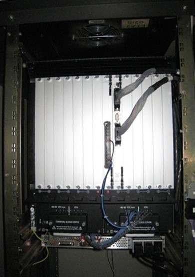
IPFN contribution for JET gamma-ray diagnostics was the design, development and integration of two similar real-time fast DAQ systems based on ATCA. The figure presents the JET CODAS cubicle for KN3G DAQ system.
The ATCA based real-time fast DAQ systems, developed at IST and installed at JET are composed by a commercial ATCA shelf, an ATCA controller (ATX motherboard linked to a PCI Express (PCIe) switch through x16 PCIe lane), and fast digitizers modules to cover the diagnostics channels. It may also include a commercial ATM module for connecting to the JET real-time network.
The fast digitizers (SR-TR-ATCA) include 4 GB DDR2 SODIMM, 2 Virtex 4 FPGA (XC4VFX60/1152), and 8 ADC channels of:
(a) 14-bit resolution with a sampling rate up to 400 MSPS or
(b) 13-bit resolution with a sampling rate up to 250 MSPS
The choice of (a) or (b) depends on the application requirements.
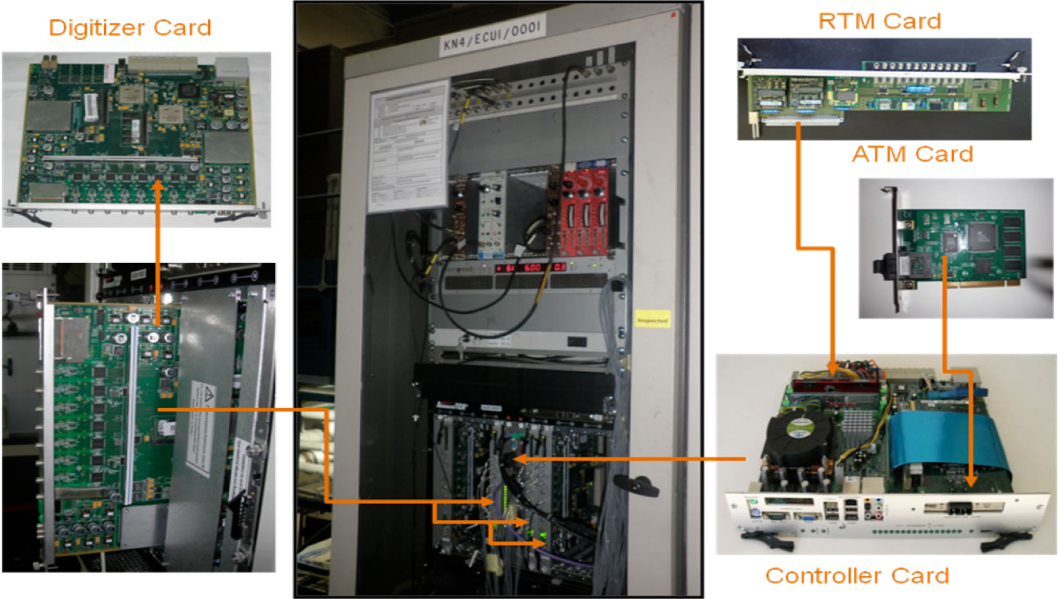
Figure: JET CODAS cubicle for KN3G DAQ system
JET hard X-ray and gamma ray profile monitor (KN3G diagnostic):
The new ATCA DAQ system, installed to measure simultaneously gamma and X-rays (Fast Electron Bremstrahlung – FEB) overcoming the former FEB system (shaping amplifier + MCA) limitations, is composed by (i) an ATCA shelf, (ii) an ATCA controller module; (iii) three SR-TR-ATCA modules (ADCs version (b)); and (iv) one PCI/ATM module. The three SR-TR-ATCA digitizers are needed to accommodate data from all the 19 CsI(Tl) detectors, being able to acquire and process in real-time the line-integrated emissions of the hard x-ray (low-energy pulses) and the gamma-ray (high energy pulses) signals. Accordingly, dedicated algorithms were developed for the real-time processing at FPGAs.
With the new system it is possible to achieve continuous and simultaneous spectra, for both hard X-ray and gamma-ray signals, in an energy range from ~200 keV to ~10 MeV.
The DAQ behaviour for each plasma discharge is as follows: every time an acquisition is enabled, packets with real-time processed data are streamed, precisely at every 2ms, through PCIe links from the digitizers FPGAs to the ATCA controller. Simultaneously, data (raw or processed) is stored during the discharge in the digitizers DDR2. When the acquisition is disabled the digitizers stop sending streamed data and start sending PCIe DMA packets with the data stored in DDR2. At the end, all produced data is stored in JET database.
The Multithreaded Application real-time executor (MARTe) installed in the ATCA controller is responsible for interfacing with the JET CODAS and the JET real-time ATM network. The counts in pre-defined energy windows of the most relevant channels, obtained from the streamed processed data coming from the FPGAs in each 2ms, are used to build the datagram which is sent periodically (each 2ms) through the ATM network, foreseeing control purposes.
JET Gamma-Ray Spectrometer Upgrade (GSU)
JET gamma ray camera is now equipped with the state of the art high resolution/high count rate compact gamma spectrometers. Our main goal is to combine tomography with spectroscopy information allowing the reconstruction of fast ion profiles and the energy distribution of runaway electrons during Deuterium-Tritium experiments. As responsible by the GCU DAQ, we made a complete upgrade in the former system. We studied and implemented advanced real-time processing algorithms at DAQ FPGAs, capable to sustain the expected high count rates without losses. We successfully tested the DAQ upgrade during the installation of detectors in both horizontal and vertical cameras. Our next steps are the validation of DAQ operation, from interaction with detectors up to its interface with CODAS, during the commissioning phase and plasma operation.
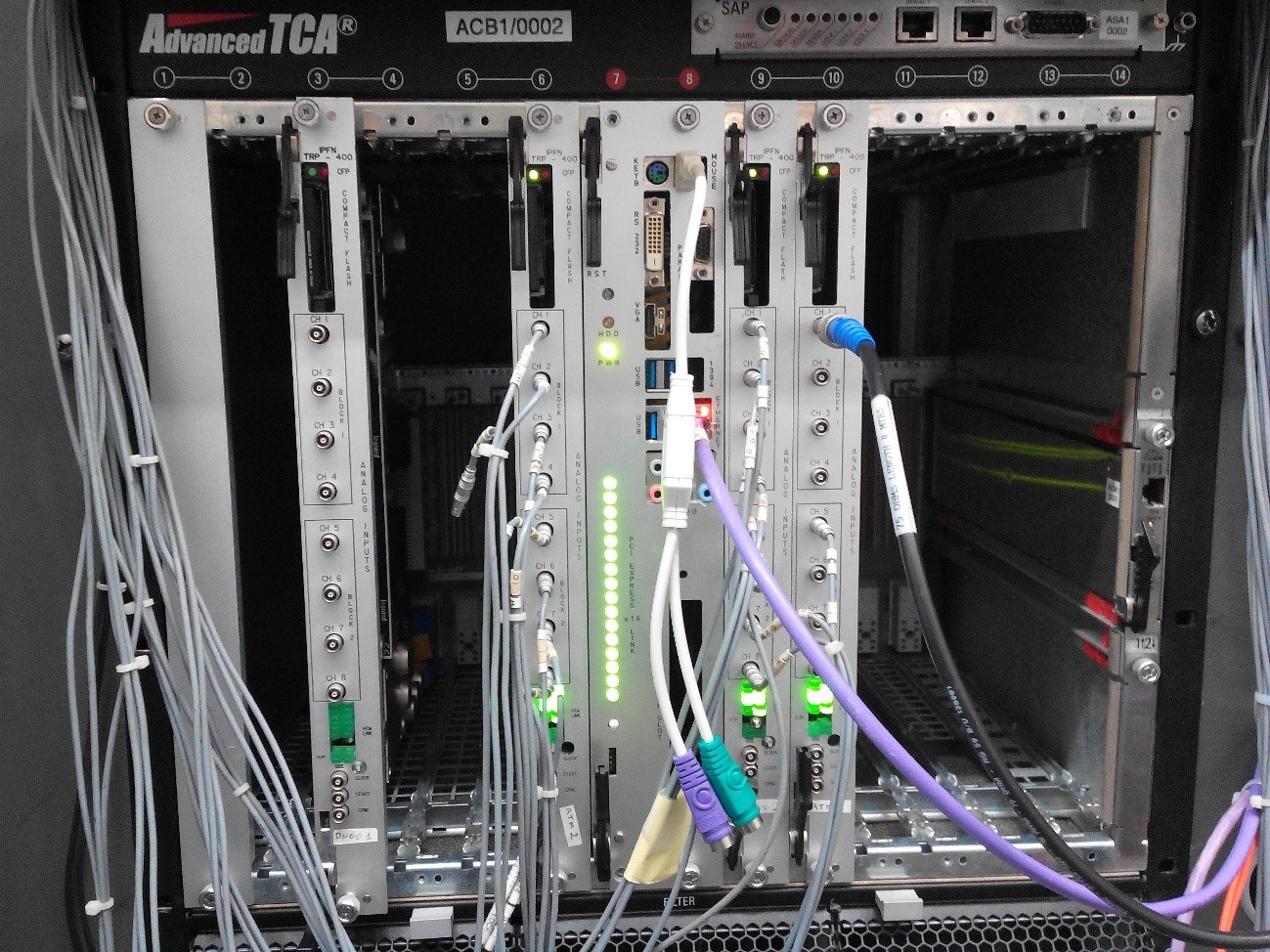
Figure: DAQ developed by IPFN installed in GCU cubicle at JET and connected to the 19 detectors of gamma camera.
Jet Gamma-Ray Spectroscopy (KM6S diagnostic)
The diagnostic is used to perform high-resolution gamma-ray spectroscopy (4 to 20 MeV) at very high count rate up to few MHz (~5MHz). To cope with the high count rate and high-resolution of the KM6S spectrometers (LaBr3(Ce) detectors), the new DAQ is composed by (i) an ATCA shelf, (ii) an ATCA controller; (iii) one SR-TR-ATCA module (ADCs version (a)) to acquire data from two spectrometers.
An implemented FPGA algorithm, the event selection algorithm, can be used for detecting events (pulses) triggered by predefined thresholds, and to store data corresponding to the triggered event, avoiding noise peak-up.
During acquisition data (raw or events) are stored in the digitizers DDR2. When the acquisition is disabled the data stored in DDR2 is sent to the ATCA controller and retrieved to JET database. The diagnostic is not connected to the JET real time network.
JET Gamma-Ray Spectrometer Upgrade (GSU)
The project goal is to enable the JET horizontal gamma-ray spectroscopy diagnostic for alpha-particle measurements during the Deuterium-Tritium experiments, by replacing the existing diagnostic with new detector modules and a new digital DAQ developed by IPFN. We successfully installed and integrated the DAQ in diagnostic cubicle and with CODAS. We made studies allowing to demonstrate the capability to operate at count rates over 2 MHz. We also developed and implemented at DAQ FPGAs a real-time algorithm capable to sustain those rates without losses. Our next step is to test the DAQ with detectors in place during the commissioning phase and with plasma.
EUROfusion Projects
Magnetic control tools for the operation of JT-60SA
Project Leader: Nuno Cruz
The fusion electricity roadmap to the realization of fusion energy aims at presenting the strategy that enables the Demonstration Fusion Power Plant (DEMO) by 2050. The WP-SA project prepares the exploitation of JT-60SA in support to ITER, while complementing it regarding the key issues for DEMO.
ITER will break new ground in fusion science and the European laboratories should focus their effort on its exploitation. To ensure its success, the preparation of operation on JET and JT-60SA should be undertaken as main risk mitigation measures.
In “Fusion Electricity – A roadmap to the realisation of fusion energy”, F. Romanelli et al., EFDA, 2012
The importance of the current work comes from the fact that to accomplish the goals set by JT-60SA project, it is necessary to achieve the designed plasma performance with the help of magnetic control tools that carry out the necessary plasma shape, current and position control. In preparation for a steady-state fusion power plant it is required an accurate plasma boundary control, with high triangularity and vertical elongated shapes. These characteristics permit to achieve high plasma kinetic energy to magnetic energy ratio, aiming at increasing the plasma density and plasma confinement time. Moreover, high elongated plasmas are vertically unstable, demanding a dedicated fast vertical stability closed loop controller that does not interact with the shape and current controllers.
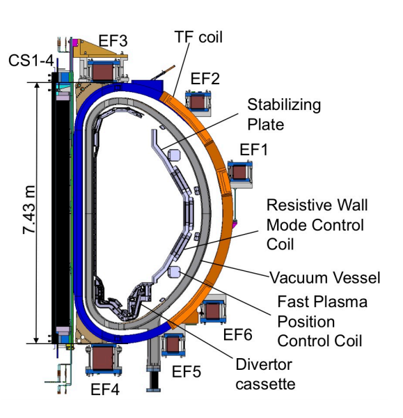
Schematic cross-section of the JT-60SA Tokamak
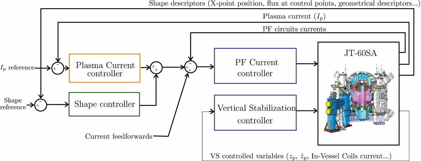
Proposed architecture for the JT-60SA Magnetic Control System
Development of an innovative diagnostics concept for DEMO
IPFN developed a first design of an innovative concept for the integration of several groups of antennas and waveguides into a full poloidal section of the DEMO breading blankets, dedicated to reflectometry.
The system was studied in detail, including a preliminary design of a liquid-helium cooling system. Nuclear and thermal analyses were performed for this model, using the state-of-the-art simulation codes MCNP6 and ANSYS Mechanical.
Results show that the direct exposure to intense neutron and photon fluxes, as well as to the thermal radiation coming from the plasma, creates hotspots in regions located further away from the cooling channels, such as the antennas and some parts of the first wall.
Apart from these hotspots, it was shown that with an adequate routing of the cooling system it is possible to lower the operation temperatures to acceptable values, even in the most exposed areas of the first wall.
Future iterations will aim at improving the design of the cooling system to increase the flow of helium in the identified hotspots.
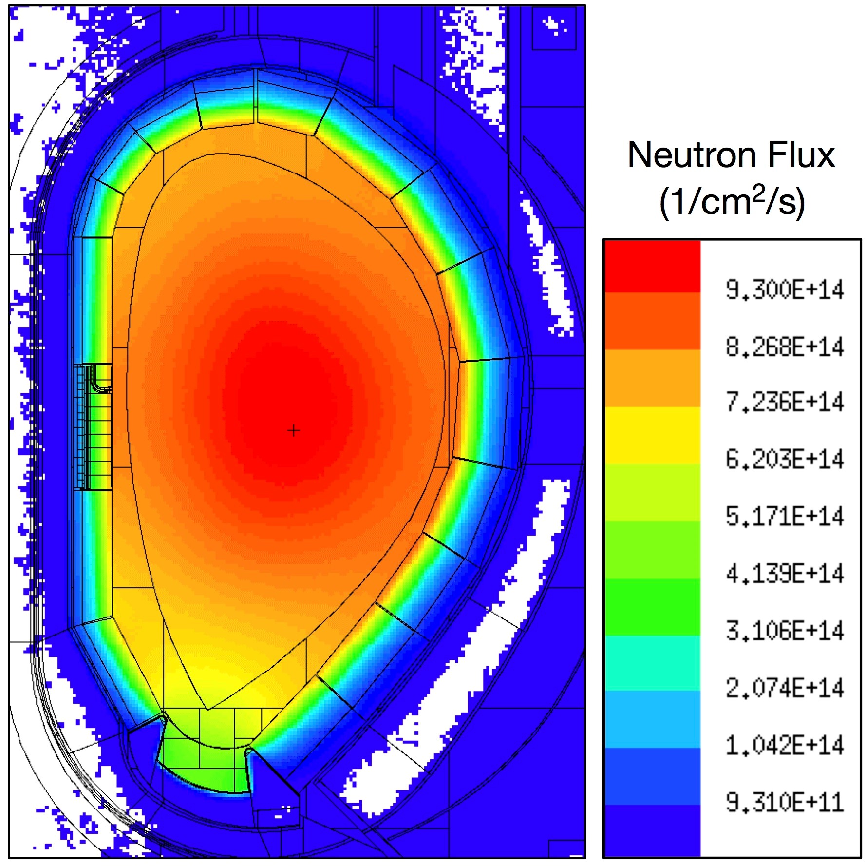
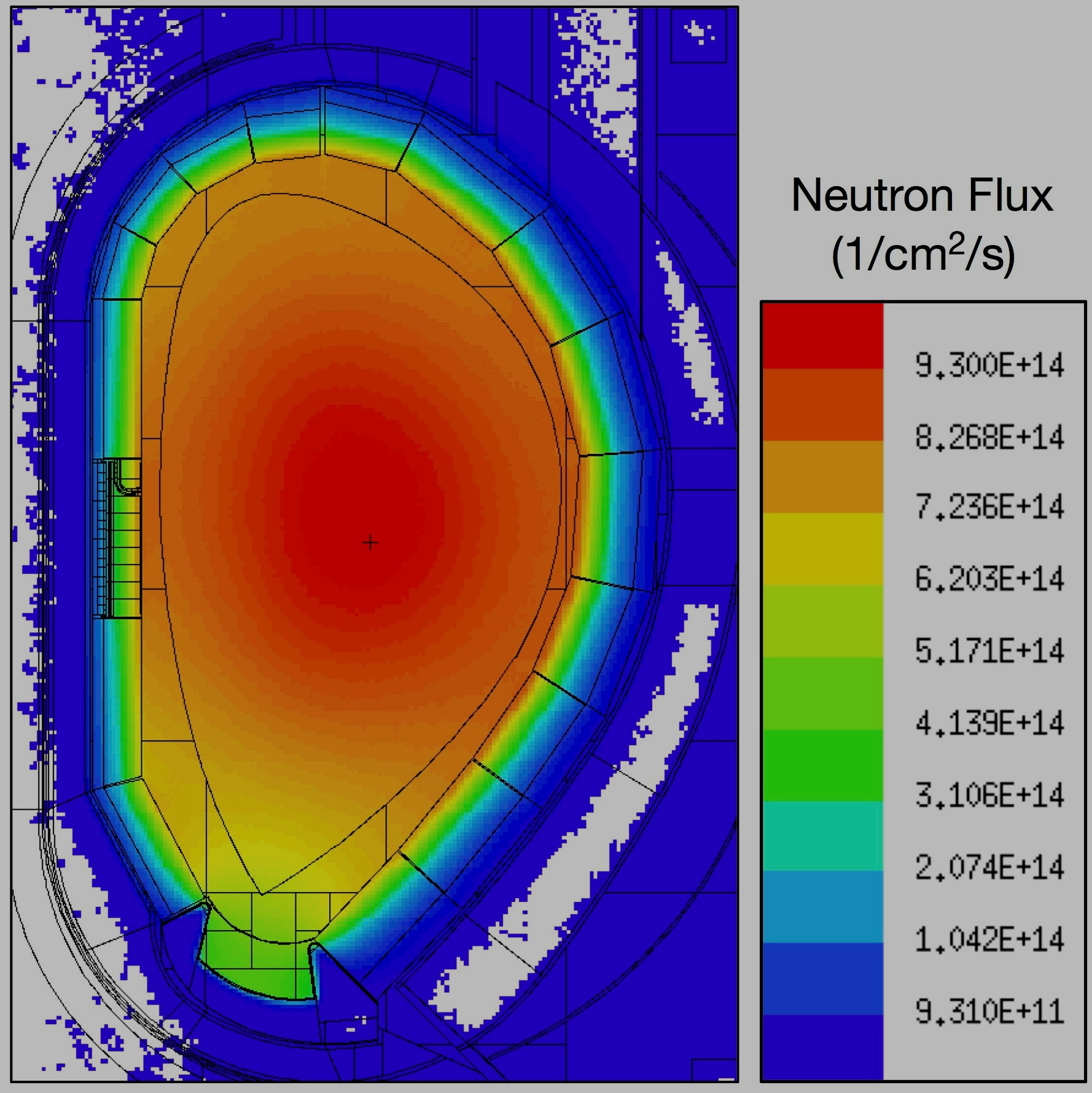
Neutron fluxes in the DEMO tokamak. The picture shows the harsh radiation environment foreseen for the DEMO tokamak, estimated using the Monte Carlo simulation program MCNP6. The materials of the reflectometry system designed by IPFN must be able to operate at extremely high temperatures and withstand neutron fluxes up to 1015 neutrons/cm2/s.
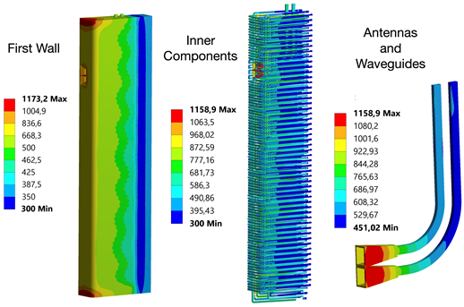
Innovative diagnostics concept developed for DEMO. The picture shows the operation temperatures (ºC) in the antennas, waveguides, shielding components and cooling system of an integrated reflectometry diagnostics system under development for DEMO. The design of an effective liquid-helium cooling system is among the most demanding challenges faced by our engineering team.
Remote Handling activities for DEMO
Since 2013, IPFN is also participating in the Remote Maintenance System of DEMO (DEMOnstration Power Plant), under the EUROfusion consortium.
The main areas of work are:- Conceptual design description of an ex-vessel transportation system. Comparison between vertical and horizontal approaches. Assessment of usage of cranes, casks and automated guided vehicles: dimensions and height, docking and transporting configurations, motion capabilities, rescue and recovery operations. Impact and requirements of the transportation system to the reactor building and Active Maintenance Facility (AMF).
- Preliminary assessment of the optimized trajectories to perform the transportation operations in all levels of the reactor building of DEMO. The respective time duration and occupied volumes were estimated for all levels, taking into account different assumptions presented in the report.
- Collate/perform a FFMECA (Functional Failure Mode, Effect, and Criticality Analysis) for the transport systems and development of a recovery strategy for all casks and cranes.
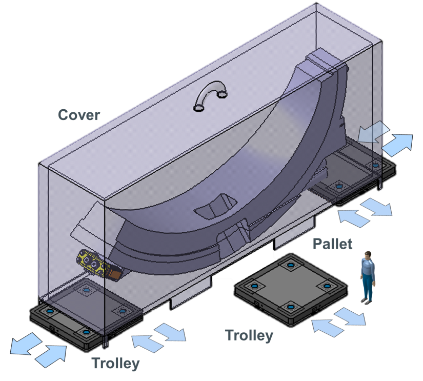
Proposed design for the cask transportation system for DEMO
ASDEX Upgrade Projects
Multichannel X-mode reflectometer system for ASDEX Upgrade ICRH antenna
Project Leader: António Silva
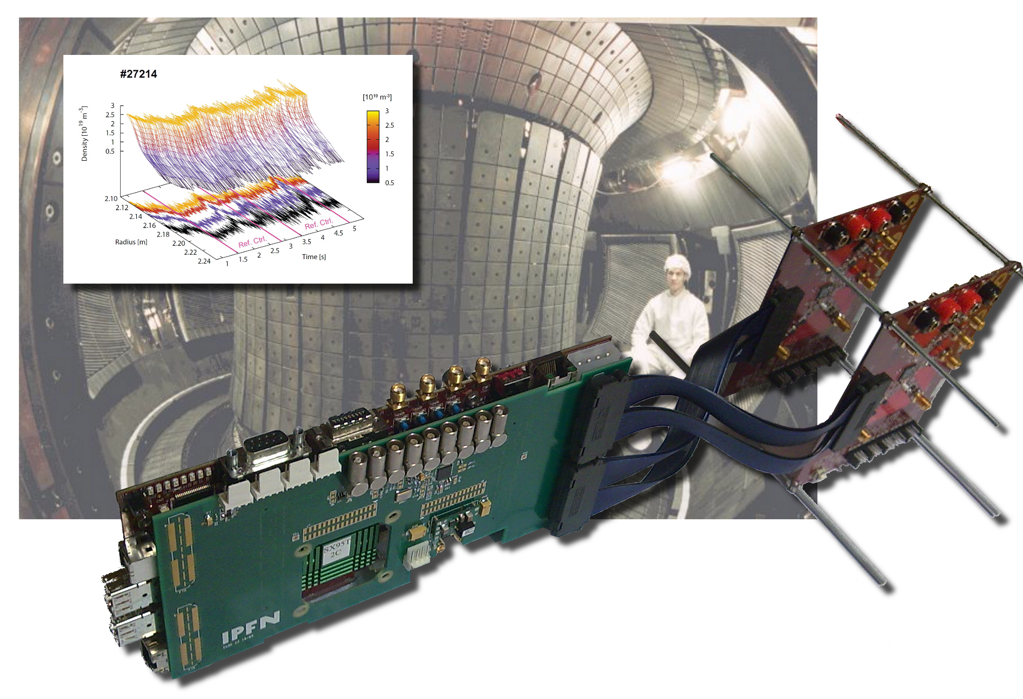
A new multichannel X-mode reflectometer system has been successfully installed and commissioned on ASDEX Upgrade to measure the plasma edge electron density profile in front of the ICRF antenna. ICRF power coupling, operational effects and poloidal variations of the plasma density profile can be consistently studied for the first time.
This project is the result of an international collaboration between IPFN, ENEA, Italy, and ASDEX Upgrade, Germany, and with the cooperation of PhD student (Diogo Aguiam) under the IST APPLAuSE doctoral programme. The IPFN team collaborated on the different design stages of the project and was responsible for the development and implementation of the microwave electronics for the emitting and receiving modules of three reflectometer channels, using a coherent heterodyne quadrature detection. The plasma is probed using three of the ten pairs of antennas installed at different poloidal locations inside the ICRF antenna. The probing frequency is swept from 40 to 68 GHz, measuring edge electron density profiles up to 1019 m-3.
The IPFN team provided a 200 MS/s eight channel data acquisition system capable of acquiring the entire 10 s of the ASDEX Upgrade plasma discharge.
The data analysis software necessary to reconstruct the electron density profiles was also developed by IPFN and preliminary density profile data has been validated with other diagnostics.
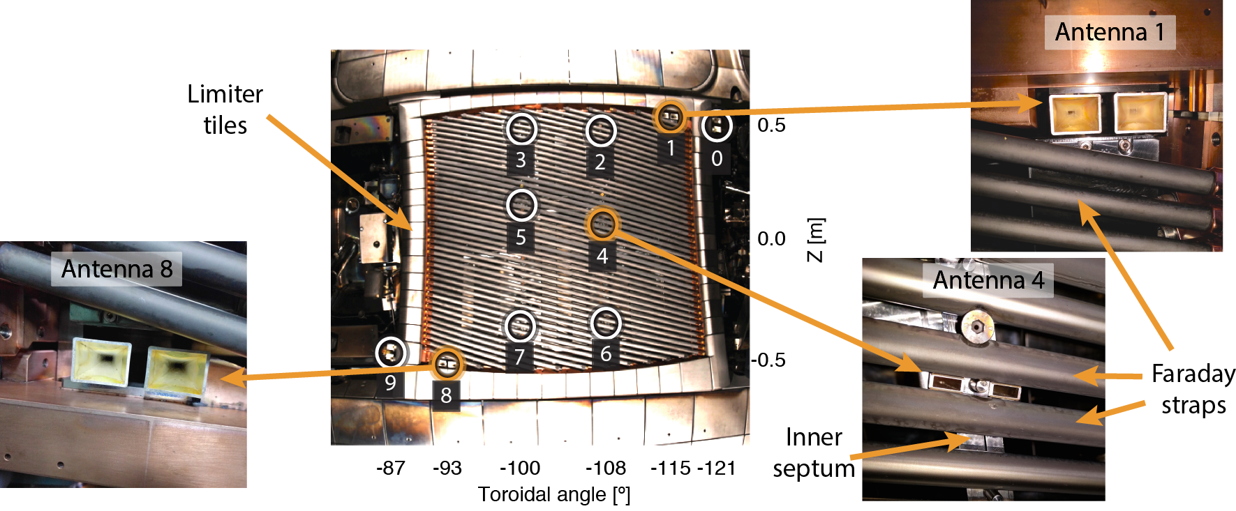
Location of the three reflectometry observation points in front of the ICRF antenna #4 at ASDEX Upgrade.
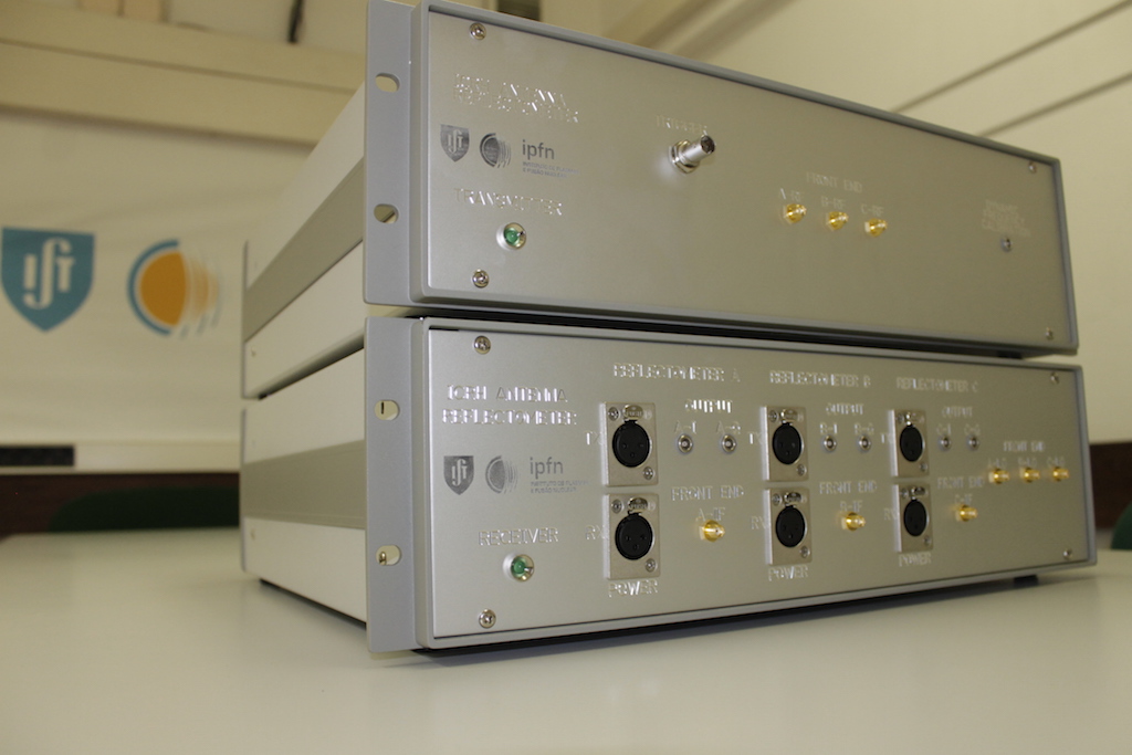
Assembled emitting and receiving reflectometer modules prior to installation at ASDEX Upgrade
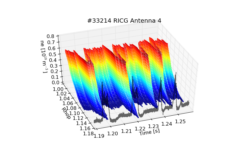
Density profile evolution in front of the ICRF reflectometry antenna located in the midplane during ELM events compared with the Divertor Shunt Current.
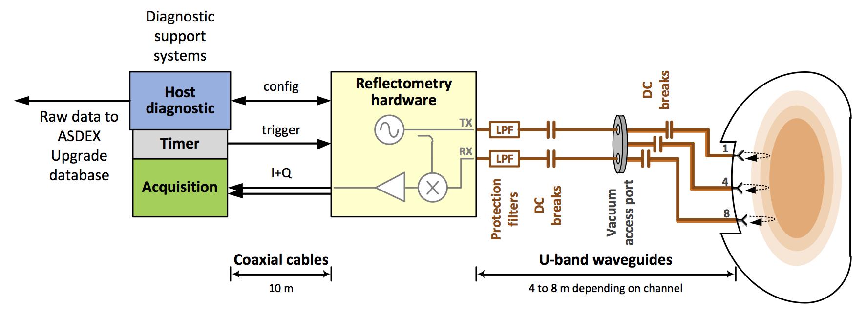
Experimental setup of the multichannel reflectometer
ASDEX Upgrade Plasma Position Reflectometry (PPR) Diagnostic
Project Leader: Jorge Santos
ASDEX Upgrade has been since 2011 been the test bed for a novel alternative technique of plasma position feedback control, relevant for future plasma fusion reactors, in particular for ITER and DEMO.
O-mode FM-CW reflectometry, a non-magnetic stand-alone technique capable of measuring the radial electron density profile, has been proposed to complement the magnetic measurements usually used for control purposes. ASDEX Upgrade (AUG) provides a unique test bed to demonstrate the viability of this new control technique due to its ITER relevant plasmas and advanced feedback control system, and to its unique FM-CW O-mode reflectometer (designed and operated by IPFN) capable of probing simultaneously the plasma at the inner and outer tokamak midplane, at 2 lines of sight (LOS) similar to ITER’s gaps g3 and g6 PPR LOS.
Similarities between AUG’s and ITER’s PPR setups, and PPR control scheme.
This project evolved in four main phases:
- Real-time measurement development phase
Real-time (RT) data processing algorithms development and optimization. RT technique validation with experimental data. - Control technique operational demonstration phase
RT reflectometry diagnostic’s hardware and software development and diagnostic integration in the AUG’s RT diagnostic network and discharge control system.
This phase led, in July 2011, to the first ever demonstration of plasma position control using reflectometry. - ITER PPR like operational demonstration phase
This phase is focused in further develop the reflectometry diagnostic to upgrade all system hardware and software, to demonstrate its control performance in an improved more ITER like operational mode.
This phase led, in April 2016, to the second demonstration of plasma position control using reflectometry, using both HFS and LFS lines-of-sight. - PPR for advanced plasma control phase
Further development of the RT reflectometry diagnostic to produce other plasma parameters relevant for advanced plasma control (HFSHD detection, pedestal density and gradient tracking, etc).
Project phase presently underway (starting phase 2018-2019).
ASDEX Upgrade plasma position control demonstrations (phases 2 and 3)
This is a highly multidisciplinary project. Among other tasks it involves the development and experimental validation of advanced real-time digital signal processing techniques, the development of a very high data-throughput PCIe data acquisition system, the implementation of the developed algorithms and diagnostic support software using advanced parallel programming techniques, the integration and optimization of all the software in NUMA based multi-core, multi-CPU systems using RT patched Linux kernels and the development of all the required reflectometry system control software and data visualization and configuration GUI tools. Thus, its success depended/depends on mastering numerous areas from both Technological Physics Engineering and Electrical and Computer Engineering fields, namely:- Microwave reflectometry
- Experimental plasma diagnostic exploitation
- Data signal processing
- Neural Networks
- Parallel processing
- FPGA programming
- Advanced data acquisition system development
- RT operating systems (configuration and optimization)
- Advanced programming languages
- GUI data visualization and system configuration tool development
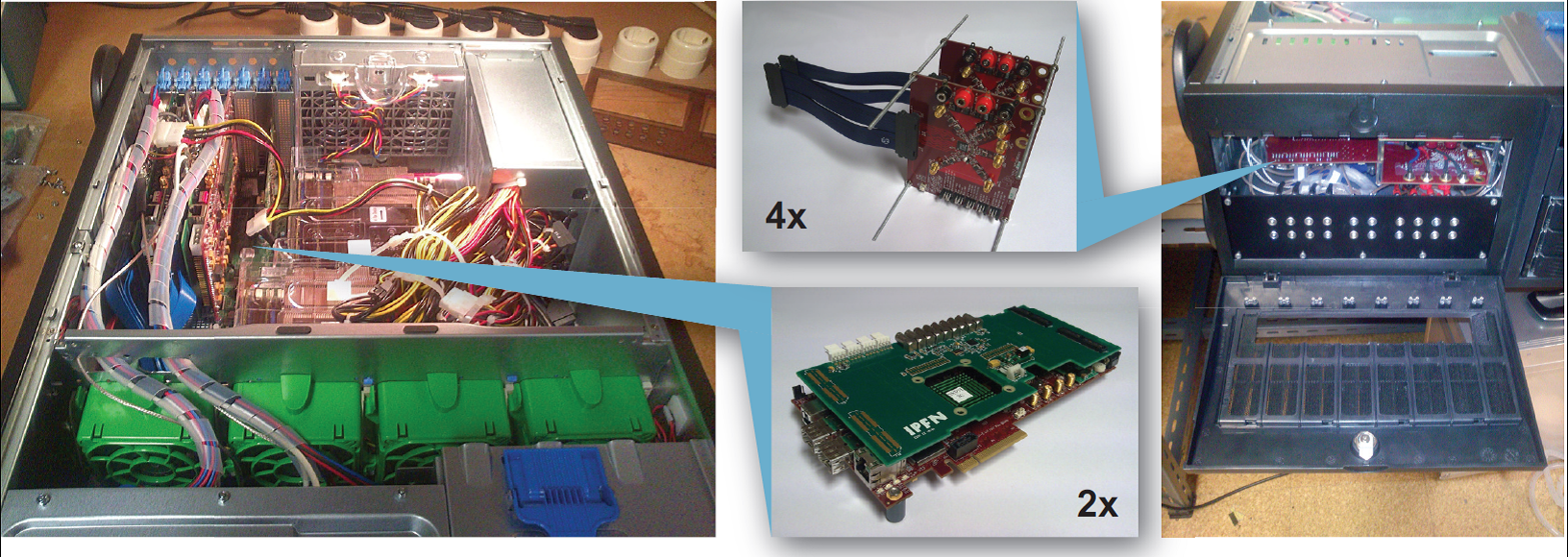
Custom designed very high data throughput RT data acquisition system.
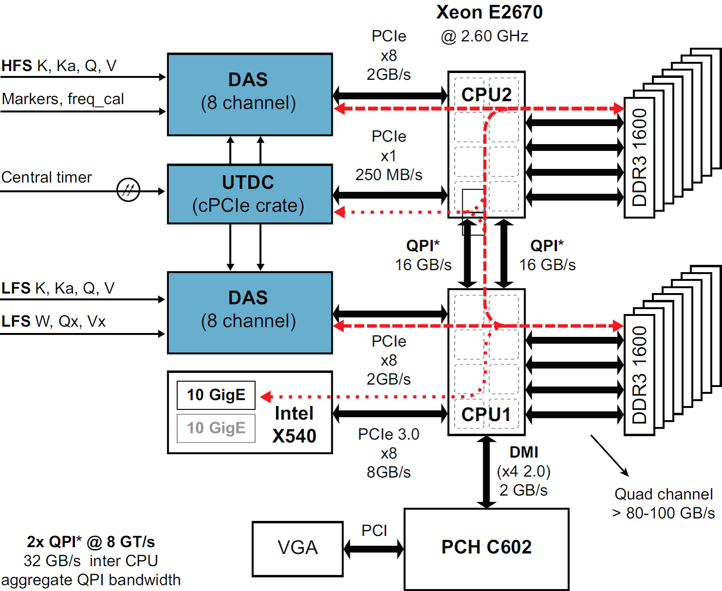
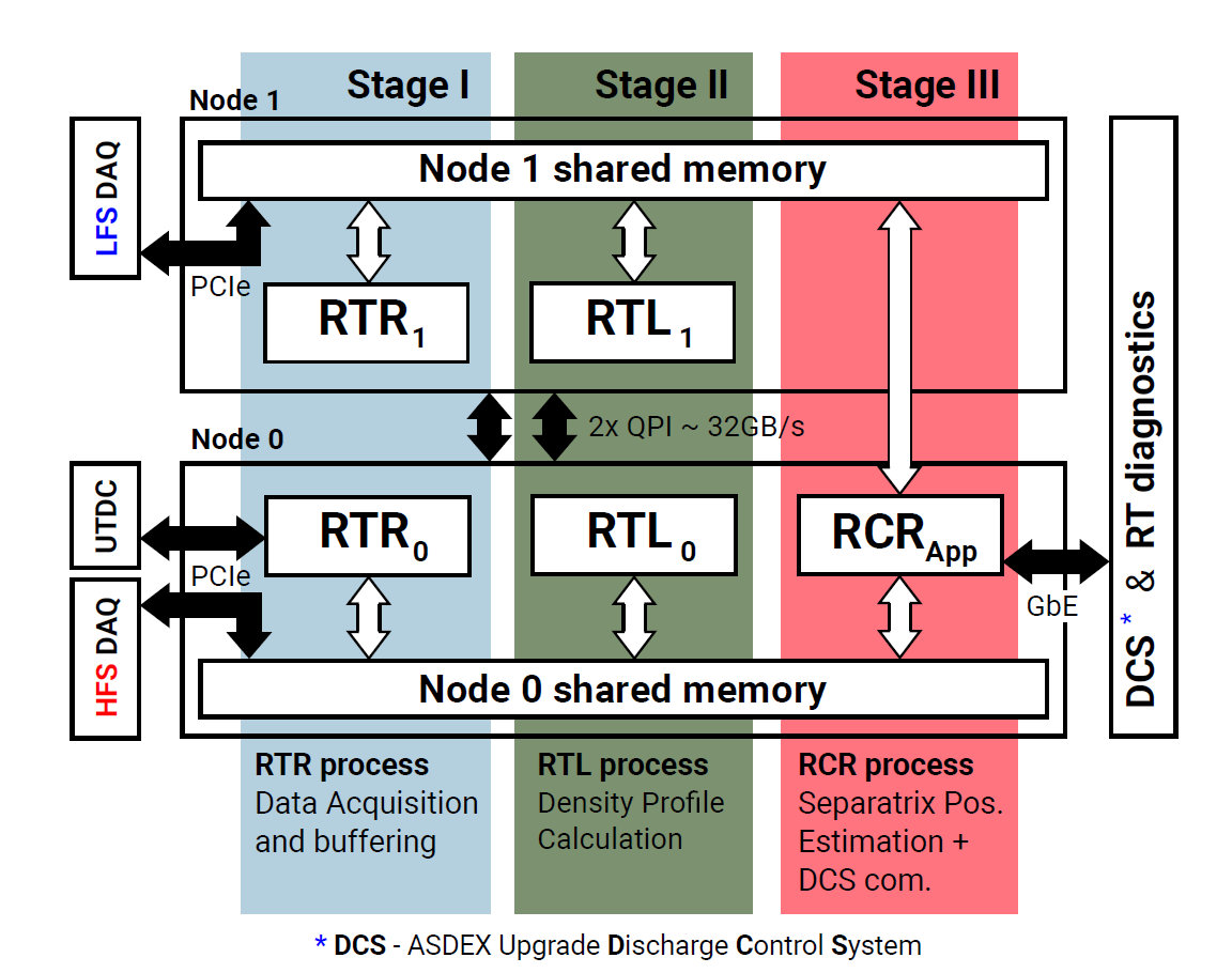
RT system architecture and NUMA based parallel data processing software implementation.
This project, proposed and led by IPFN, was awarded several grants. Phase 2 started with the priority support awarded by the European Fusion Development Agreement (EFDA) to the project, due to its ITER relevance, under tasks WP08/09-DIA01-01 e WP10-DIA-01-03. Phase 3 demonstration was supported by EUROfusion grants AUG14-1.8-3 and AUG15-1.8-3, under the Medium-Size Tokamaks MST1 programme.
Apart from numerous publications generated by the project, it received so far the following prizes and scientific media coverage:
- Scientific Prizes:
- Media coverage:
- Successful operation of plasma position control system using microwave reflectometry (IPFN Press Release – 2 Outubro 2011)
- ASDEX: new approach to plasma position control (ITER newsline 191 - 23rd September 2011)
- Keeping the plasma in place with microwaves (Fusion in Europe – 19th December 2011)
- Investigadores portugueses "aprisionam o Sol" (GAeA Astronomia / Ciência Hoje – 28 Setembro 2011, portuguese)
- "Com Ciência" RTP2 TV science programme – 12 Dezembro 2012 (by 2:30, portuguese)
- Plasma Position Control using Electromagnetic Waves (IPFN Press Release – 5 Maio 2016)
FCT Projects
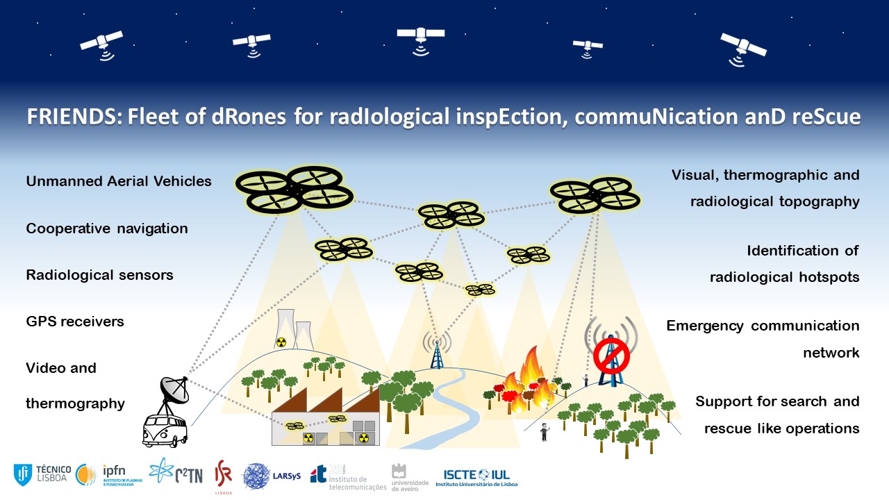
Fleet of dRones for radIological inspEction, commuNication anD reScue (FRIENDS)
Project Leader: Alberto Vale
The quick characterization of the geographic extent of radiological contamination is a key problem in hazard scenarios, such as nuclear terrorism and accidents, for the guarantee of public health. This project addresses this challenging problem by proposing a fleet of drones to perform this characterization, in particular, focused on these challenges:
- real-time mapping of both the scenario and the contamination level of a given area,
- autonomous and cooperative navigating a fleet of autonomous drones, covering this area in an optimal way, in closed loop with the real-time construction of the contamination map, while maintaining exposure of the drones to radiation at a safe level, and
- assuring an effective and resilient wireless data communication among the drones and the ground station.
The objectives of the project are to design, develop and validate a fleet of drones equipped with navigation and radiological sensors for inspection and monitoring of scenarios with nuclear threats. The fleet under a cooperative navigation system is able to map the scenario, localize and quantify the sources of radiation and thus evaluate the level of threat. The communication is important to remotely manage and control the fleet and, at the same time, acquire the maximum information. In case of disaster, the fleet is able to support an emergency network communication channel to establish the interface between elements in the field and the outside world. The communication system shall be designed to optimize the coverage, redundancy, security, range and bandwidth.
The synergy of the IST research labs involved (IPFN, ISR, C2TN and IT) will be exploited for a success of the project, given their experience and background on nuclear science, robotics and communications. In addition, the campus of IST in C2TN, provides excellent test facilities with a controlled storage building of activated components to perform validation of the developed solution.
Other Projects
High Availability Instrumentation
The Instituto de Plasmas e Fusão Nuclear (IPFN) of Instituto Superior Técnico, has been developing since 1990 a vertical strategy in R&D in Instrumentation and Digital Computation
IPFN work has been focused in the following areas:
- Specification and Project of Control and Data acquisition Systems;
- Hardware for Control and Data acquisition;
- Software for Control and Data Acquisition;
- Algorithms for Signal Processing;
- Computation and Parallel Processing;
- Communication and transport of timing and real-time events networks.
Transversely to this areas and incorporating the R&D results, several Nuclear Fusion projects were developed, in collaboration with EURATOM and Fundação para a Ciência e Tecnologia (Portugal), in the following scientific domains:
- Visible, X-rays, gamma-rays and neutron spectroscopy;
- Microwave reflectometry;
- Thomson Scattering;
- Plasma Tomography;
- Systems and tools for real-time control of fusion plasmas;
- Control and Data Acquisition Systems;
- Cluster’s e parallel computation.
Specification and Project of Control and Data Acquisition Systems/
IPFN specifies and projects control and data acquisition systems for nuclear fusion experiments, for the European laboratories (JET-EFDA, IPP-Garching, CIEMAT-Madrid, CRPP-Lausanne, IPP.CR-Prague) and Brazilian (INPE e USP), being presently involved in the specification of control and data acquisition systems for ITER.
Control and data acquisition hardware/
IPFN develops control and data acquisition hardware with the aim of providing the projects with modules and systems with adequate performance and characteristics. The specifications are dictated by the specificities of the experiments, and are usually not available in the industry. Other objectives are cost reduction, good reliability and maintainability.
The developed hardware is based on industrial standards (VME, PCI, ATCA …) with state-of-the-art components (DSPs, FPGAs, DDR2 …) being planed the quality certification in collaboration with ISQ (Instituto de Soldadura e Qualidade).
Control and data acquisition software/
IPFN developed a platform for control and data acquisition hardware, FireSignal, available in Linux and Windows operating systems. This software allows the control of experiments in the usual sequence of parameterization, start/end and data collection, as well as continuous control, based on event management. The platform was developed according to a distributed topology and consists in two or more servers containing the parameterization database and collected and/or processed, to which several clients are interconnected by several data transport networks. The clients are the system operators (local or remote and controlling several or the same experiment) as well as the computers that contain the control and data acquisition hardware. The capacity of participation and remote operation of experiments as well as the support for collaboration and remote communication is native to FireSignal and it is managed through a user interface which congregates all the functions.
Algorithms for signal processing/
IPFN presently develops algorithms for signal processing in the areas of spectroscopy, microwave reflectometry, tomography and control in fusion plasmas. The codes are developed for processors with algorithm parallelization capacity (FPGAs and DSP farms) as well as conventional processors.
Computation and parallel processing/
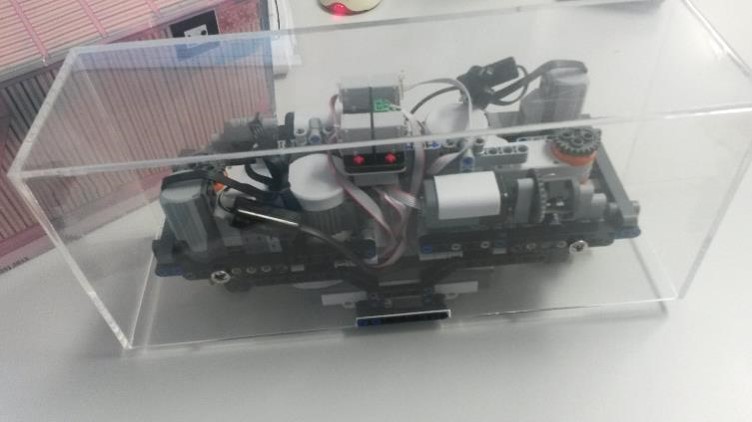
IPFN developed a computer cluster based on low cost PCs motherboards aimed at the teaching of parallel processing techniques in plasma physics. 3 shows the cluster’s hardware. IPFN is presently collaborating in the development of a GRID computational structure for the European fusion community.
Networks and real-time transport of timing and events/
One of IPFN objectives is the development of a communications network which allows the simultaneous real-time transport of data and events with temporal latencies in the microsecond order or below as well as the synchronization of network nodes with a precision inferior to 100 ns. IPFN has developed a proprietary network with these characteristics (implemented in UKAEA) and is presently studying the applicability of the industrial standard 10 Gb Ethernet to this aim.
IPFN facilitiesIPFN has a stable instrumentation group. The facilities are well equipped for the development of instrumentation for control, data acquisition, real-time systems and high performance network development.
The IPFN Control and Data Acquisition Laboratory has facilities able to handle the development and production of prototypes and small series. All steps needed to the development, from the scratch, of a Control and Data Acquisition board or System are covered by the facilities equipment and specialized staff (the only exception is the physical production of the Printed Circuit Board which must be done abroad and the purchase of components).
The main development stages covered by the laboratorial facilities are:
- Engineering design of the boards (Schematics/PCB);
- Software/Firmware development;
- Solder paste printing (mask printer and pixel printer);
- Components assembling by Pick and Place machine;
- Automatic soldering;
- Testing.
ATCA is the most promising architecture to substantially enhance the performance and capability of existing control and data acquisition systems as it is designed to handle tasks such as event building, feature extraction and high level trigger processing. It is the first commercial open standard designed for high throughput as well as availability (HA). The high throughput features are of great interest to data acquisition physics, while the HA features are attractive for experiments requiring a very high up-time.
The PICMG 3.0 Advanced Telecommunications Architecture (ATCA) standard was originally conceived to specify a carrier grade-based system infrastructure for telecommunications. It was designed from ground-up for high availability (redundant power supplies, shelf management of temperatures and fans …) and scalability.
Compared to the VMEbus which was conventionally used in data acquisition systems, the ATCA standard offers advantages especially with respect to communication bandwidth and shelf management. The ATCA carrier-blade form factor supports well-balanced systems, delivering teraOPS of processing power in a single sub-rack. The architecture is flexible as to the types of processors that can co-exist in the system. One of the most critical aspects of implementing the ATCA architecture is the ability of high-performance blades to communicate with each other, so that vast quantities of data can be moved from board to board through the switch fabric within an ATCA system.
| ATCA | VPX | cPCI Express | |
|---|---|---|---|
Dimensions |
8U |
3U and 6U |
3U and 6U |
Nr analogue channels |
32 |
16 |
16 |
Fabric |
Agnostic |
Agnostic |
PCI Express |
Backplane |
Full-mesh |
Full-mesh |
Star |
RTM |
Yes |
Yes |
Yes |
Mezzanines |
Yes |
Yes |
Yes |
Power dissipation/slot |
200 W |
Shelf |
Shelf |
Redundant power |
Backplane |
External |
External |
Redundant cooling |
Yes |
No |
No |
Hot swap |
Yes |
Yes |
Yes |
Shelf management |
Redundant |
IPMI |
IPMI |
EMC shielding |
Yes |
Yes |
Yes |
Availability |
99.99% |
- |
- |
Foreseen main |
Telecom |
Military |
Industry |
Table I: Comparison of technical features between ATCA and its direct competitors |
|||
The ATCA base specifications define Shelves (sub-rack), Boards (SBC, IO, Hub/switching, Mezzanines Carrier), Mezzanines (AMC, PMC) and Management interface sharing a common backplane with interconnections based on a full mesh of serial gigabit communication links.
Each slot can be interconnected to all others through x1, x2 and x4 links with a maximum throughput capacity of 800 MByte/s. By choosing the correct links, it is possible to have more than one controller on the ATCA shelf, each controlling a set of ATCA digitizer modules.
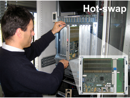
The ATCA redundancy scheme permits to have two equal sets of cards installed on the shelf and in case of failure of the operating set, the second one can take over its functions. ATCA is also capable of hot-plugging of cards thus allowing continuous operation and maintenance.
Supported communications protocols are the Advanced Switching Interconnect (ASI), PCI Express (PCIe), Gigabit Ethernet (GbE), Serial RapidIO (SRIO), Infiniband or other PICMG 3 compliant standards. Each slot is interconnected to all others through x1, x2 or x4 links with a maximum real throughput capacity of ~800 MByte/s (10 Gbit/s per link – 25 Gbit/s per link supported).
ATCA platform highlights:
- Scalable shelf capacity to 2.5Tb/s;
- Each slot is interconnected through up to four 2.5 Gb/s links with an actual throughput capacity of ~800 MByte/s per link;
- Scalable system availability to 99.999%;
- Multi-protocol support for interfaces up to 40 Gb/s;
- Robust power infrastructure (distributed 48V power system) and large cooling capacity (cooling for 200W per board);
- High levels of modularity and configurability;
- Ease of integration of multiple functions and new features;
- The ability to host large pools of DSPs, NPs, processors and storage;
- The ability to host multiple controllers and storage on a shelf (blade servers and DSP farms);
- Advanced software infrastructure providing APIs and OAM&P;
- High security and regulatory conformance;
- Supports 14 slots shelves in 19” cabinet;
- Large enough board for low cost;
- Reliable, full redundancy support;
- Reliable mechanics (serviceability, shock and vibration);
- Hardware management interface.
AdvancedTCA Standards:
- PICMG 3.0: Base Specification wich covers mechanical, power, cooling, interconnect of the AdvancedTCA family of specifications;
- PICMG 3.1: Ethernet and Fiberchannel Transport;
- PICMG 3.2: InfiniBand Transport;
- PICMG 3.3: StarFabric Transport;
- PICMG 3.4: ASI and PCI Express Transport;
- PICMG 3.5: Serial RapidIO Transport.
Additional ATCA related specifications:
- Advanced Mezzanine Card (AMC);
- MicroTCA.
The next generation of large-scale physics experiments will raise new challenges in the field of control and automation systems and demand well integrated, interoperable set of tools with a high degree of automation. Fusion experiments will face similar needs and challenges.
In nuclear fusion activities, e.g. JET and other devices , the demand has been to develop front-end electronics with large output bandwidth and data processing Multiple-Input-Multiple-Output (MIMO) controllers with efficient resource sharing between control tasks on the same unit and massive parallel computing capabilities. Future systems, such as ITER, are envisioned to be more than an order of magnitude larger than those of today. Fast control plant systems based on embedded technology with higher sampling rates and more stringent real-time requirements (feedback loops with sampling rates > 1 kHz) will be demanded. Furthermore, in ITER, it is essential to ensure that control loss is a very unlikely event and more challenging will be providing a robust, fault tolerant, reliable, maintainable, secure and operable control systems. ATCA is the most promising architecture to substantially enhance the performance and capability of existing standard systems delivering well high throughput as well as high availability.
The ATCA platform is gaining traction in the physics community because of its advanced communication bus architecture (serial gigabit replacing parallel buses), high availability n+1 redundancy, variety of form factors, very high data throughput options and its suitability for real-time applications. Active programs are showing up most notably at DESY for XFEL and JET but also at other laboratories such as ILC, IHEP, KEK, SLAC, FNAL, ANL, BNL, FAIR, ATLAS at CERN, AGATA, large telescopes and also Ocean Observatories . Both the CMS and ATLAS detectors are investigating ATCA solutions for future upgrades and ILC and ITER are setting up prototype experiments to test its potential. Most of these programmes put the emphasis on High Availability. In ITER, for example, ATCA is being considered for its performance but also because the systems will be located in areas of difficult access during operation.
Collaboration between laboratories and industry to achieve broad sharing of information and interchangeability of module designs is increasing. ATCA has superior technical features, for large physics experiments, than its strongest competitors VPX and CPCI Express. If an ATCA extension for instrumentation (xTCA for Physics) succeeds to appear in a short period of time, the ATCA will continue to have advantages over VPX and CPCI Express in spite of the associated evolution of VXI and PXI instrumentation.
